CBCNC — Custom Three-Axis PCB Milling Machine
A custom electromechanical motion platform built to evaluate in-house rapid PCB prototyping, multi-axis motion control, and dedicated CNC controller integration.
READ EXECUTIVE SUMMARY & SCOPE expand_more
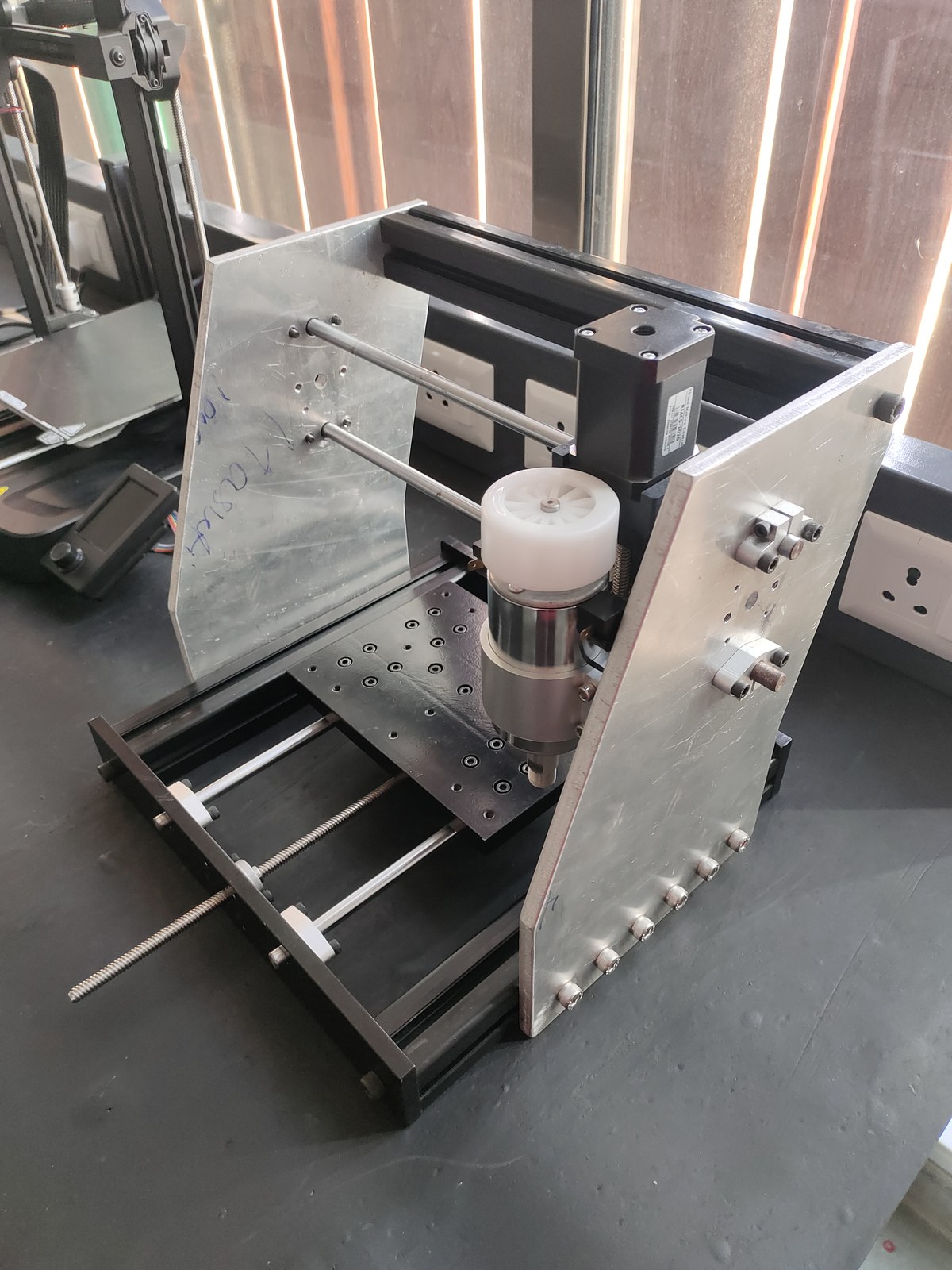
Executive Summary: CBCNC Rev 1 is a custom-designed, physically assembled three-axis desktop CNC milling prototype. Developed to explore alternatives to long external PCB fabrication turnaround times and avoid handling chemical etchants, the project served as an end-to-end electromechanical build.
It combines mechanical modeling in Fusion 360, custom 10 mm aluminum plate fabrication, a custom-designed two-layer ESP32-S3 motion controller board running FluidNC, external DM542 stepper drivers, and an RP2040 UART HMI subsystem. Multi-axis motion and spindle operation under no-load conditions were demonstrated on the bench; copper trace isolation milling, drilling, contour cutting, and stability under cutting loads remain unvalidated.
Executive Summary: CBCNC Rev 1 is a custom-designed, physically assembled three-axis desktop CNC milling prototype. Developed to explore alternatives to long external PCB fabrication turnaround times and avoid handling chemical etchants, the project served as an end-to-end electromechanical build.
It combines mechanical modeling in Fusion 360, custom 10 mm aluminum plate fabrication, a custom-designed two-layer ESP32-S3 motion controller board running FluidNC, external DM542 stepper drivers, and an RP2040 UART HMI subsystem. Multi-axis motion and spindle operation under no-load conditions were demonstrated on the bench; copper trace isolation milling, drilling, contour cutting, and stability under cutting loads remain unvalidated.
The Problem: Turnaround Latency & Chemical Handling
Commercial PCB manufacturing turnaround was too slow for the pace of experimentation I wanted. A single layout correction or schematic revision introduced days or weeks of waiting for remanufactured boards from external fabrication facilities.
Conventional chemical etching raised practical concerns regarding the handling, storage, and disposal of hazardous etchant chemicals in a student environment, alongside process variations such as trace undercutting on fine geometries.
Commercial CNC machines capable of milling PCBs were expensive, while general-purpose desktop routers were designed for general hobby cutting rather than being dedicated to PCB prototyping. Rather than compromise on a poorly suited general-purpose router, I decided to build a dedicated three-axis PCB milling machine to understand the complete electromechanical system from first principles.
Engineering Requirements: Design Targets vs. Measured Baseline
In PCB isolation milling, depth precision and mechanical stiffness are fundamental design considerations because micro-milling bits must selectively isolate 35 µm copper foil without excessive runout or tool deflection. The physical dimensions were selected around commonly available copper-clad PCB stock.
MEASURED directly on assembled machine.
TARGET ONLY: No copper cutting tests conducted.
TARGET ONLY: Operations remain to be tested.
DEMONSTRATED: Axis translation demonstrated under motor drive.
DEMONSTRATED: Screws translated motor rotation into axis travel.
DEMONSTRATED: Powered & observed rotating; audible vibration present.
MEASURED: Baseline current quantified for bearing & internal losses.
DEMONSTRATED: Axis movement & soft limits established.
UNTESTED: Circuit routed on PCB; physical switches & homing untested.
| Parameter / Subsystem | Design Target (Goal) | Physical Prototype Status | Engineering Evaluation |
|---|---|---|---|
| Usable Working Envelope | Sized for copper-clad PCB stock | Approx. 150 × 150 × 40 mm | MEASURED directly on assembled machine. |
| Trace & Clearance Target | 0.2 mm (approx. 8 mil) | Not Validated | TARGET ONLY: No copper cutting tests conducted. |
| PCB Manufacturing Operations | Isolation, drilling, contour routing | Not Validated | TARGET ONLY: Operations remain to be tested. |
| Kinematic Guidance | Precision linear shafts (Rev 1) | Functional Baseline | DEMONSTRATED: Axis translation demonstrated under motor drive. |
| Drive Transmission | 8 mm lead screws + anti-backlash nuts | Functional Baseline | DEMONSTRATED: Screws translated motor rotation into axis travel. |
| Spindle Motor | 300 W @ ~12,000 RPM nominal | Functional (Potentiometer) | DEMONSTRATED: Powered & observed rotating; audible vibration present. |
| Spindle No-Load Current | Baseline loss reference | Measured | MEASURED: Baseline current quantified for bearing & internal losses. |
| Controller Hardware | Custom ESP32-S3 PCB (FluidNC) | Functional (USB Control) | DEMONSTRATED: Axis movement & soft limits established. |
| Limit & Homing System | 6 optoisolated endstop channels | Untested Physical Switches | UNTESTED: Circuit routed on PCB; physical switches & homing untested. |
Interactive 3D Assembly Inspection
Inspect the exact Fusion 360 assemblies for both the physical Rev 1 prototype and the in-development Rev 2 redesign. Rotate, zoom, and pan directly in your browser.
Interactive 3D model (~10 MB). Rotate, zoom, and inspect Fusion 360 assemblies.
Mechanical Architecture: Fusion 360 Modeling & Physical Trade-offs
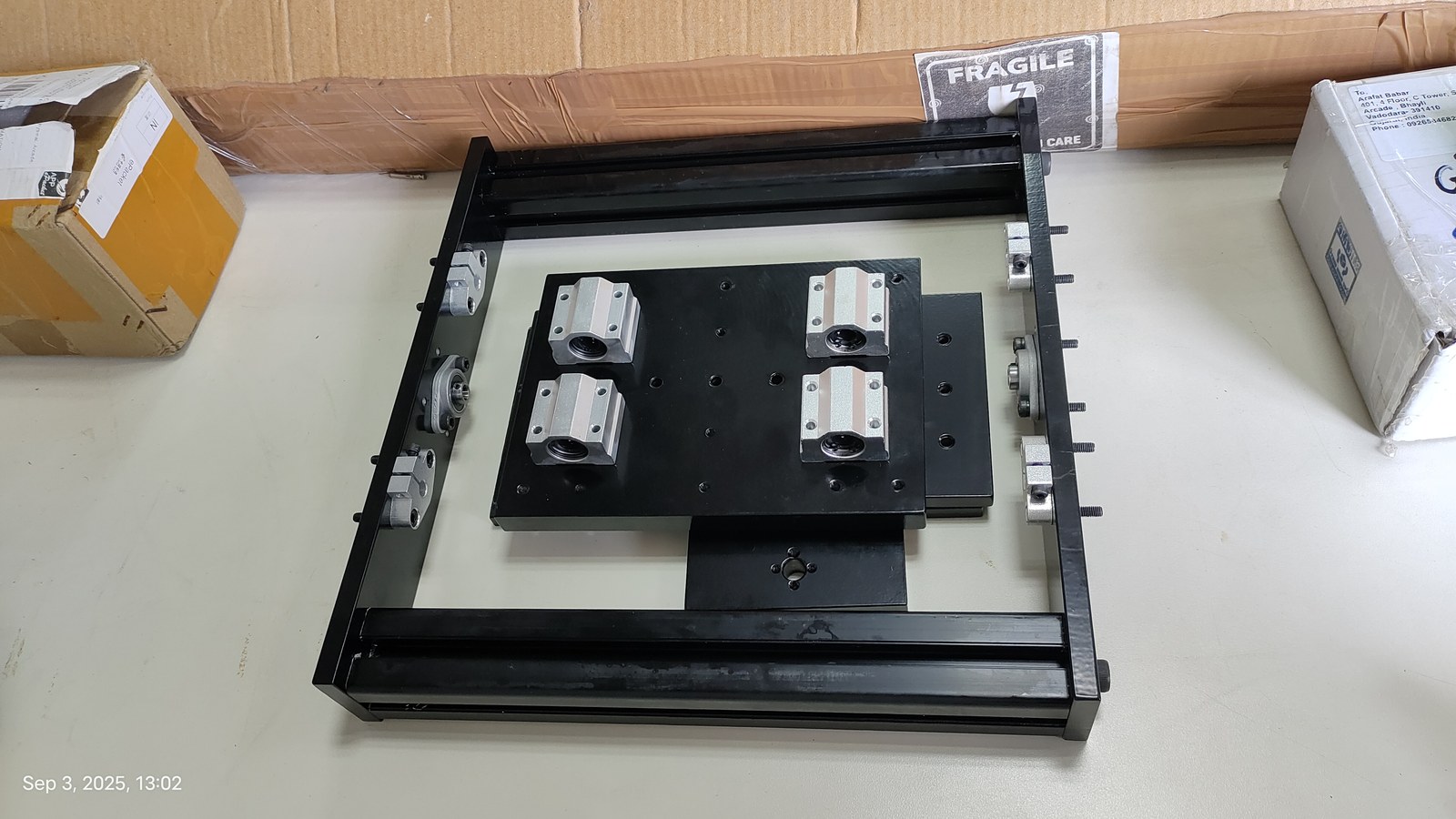
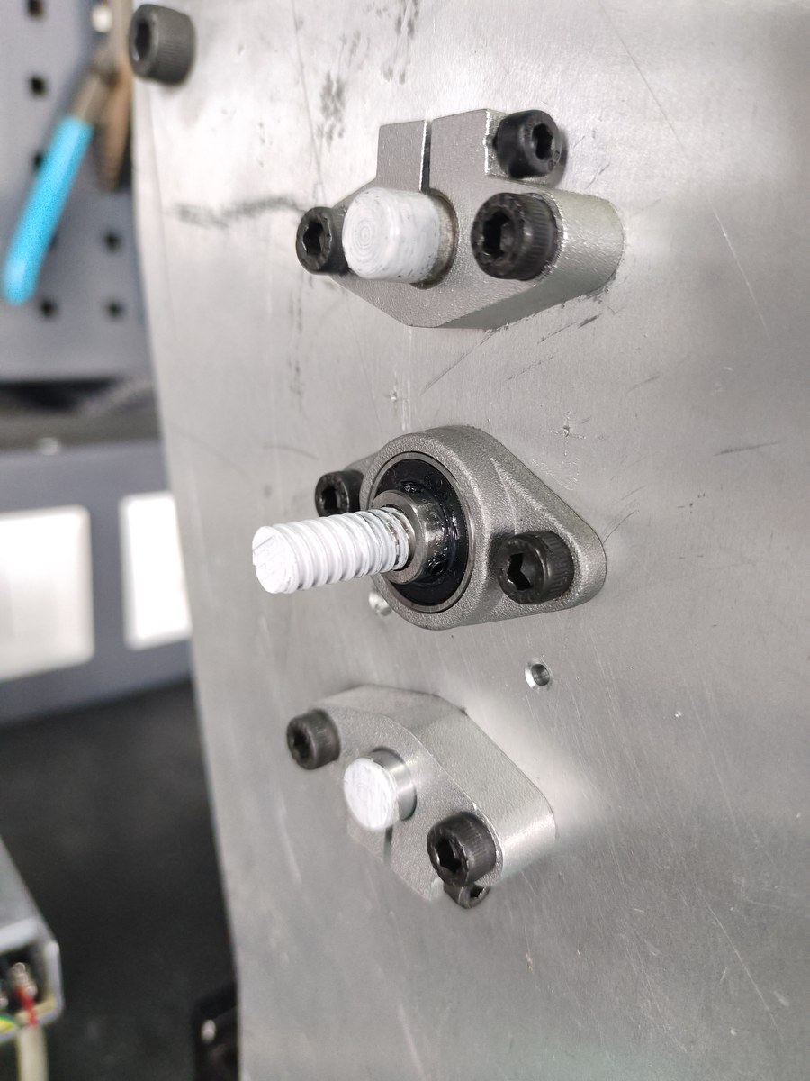
The machine utilizes a moving-gantry architecture. The stationary base frame is built from 4040 aluminum extrusion profiles joined with corner brackets. The gantry uprights are custom 10 mm thick aluminum plates, manufactured using a combination of processes, providing vertical mounting faces for the horizontal linear guide shafts and lead-screw bearing mounts.
I modeled most of the machine in Autodesk Fusion 360 and included as many real components as practical so the CAD model would closely represent the physical assembly.
- Guidance: Cylindrical linear guide shafts supported by aluminum end blocks across all three axes.
- Drive: Lead screws with a 2 mm pitch and 4 starts, yielding an 8 mm lead per revolution.
- Backlash Suppression: Lead screws paired with anti-backlash brass nuts to suppress axial play.
- Stepper Motors: NEMA 17 stepper motors rated at 8 N·cm (0.08 N·m) holding torque were selected with torque margin in mind as a deliberate design decision.
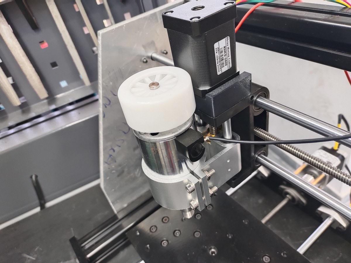
Designing the complete Z-axis mechanism was beyond my capabilities at the time. To avoid stalling the build, I made a conscious design compromise: I purchased a complete Z-axis slide module equipped with a mount for a 58 mm spindle. This allowed me to proceed with the overall assembly and focus on structural integration and electronics.
Finding a suitable high-RPM, low-power spindle was difficult. A spindle with a stated specification of 300 W at approximately 12,000 RPM was selected. The unit was purchased with a stated specification of 0.02 mm runout, but I did not independently measure the runout of the assembled machine. During testing, vibration was noticeable by ear. The exact spindle model and electrical supply details remain unconfirmed.
Electrical & Control Architecture: Custom ESP32-S3 Hardware
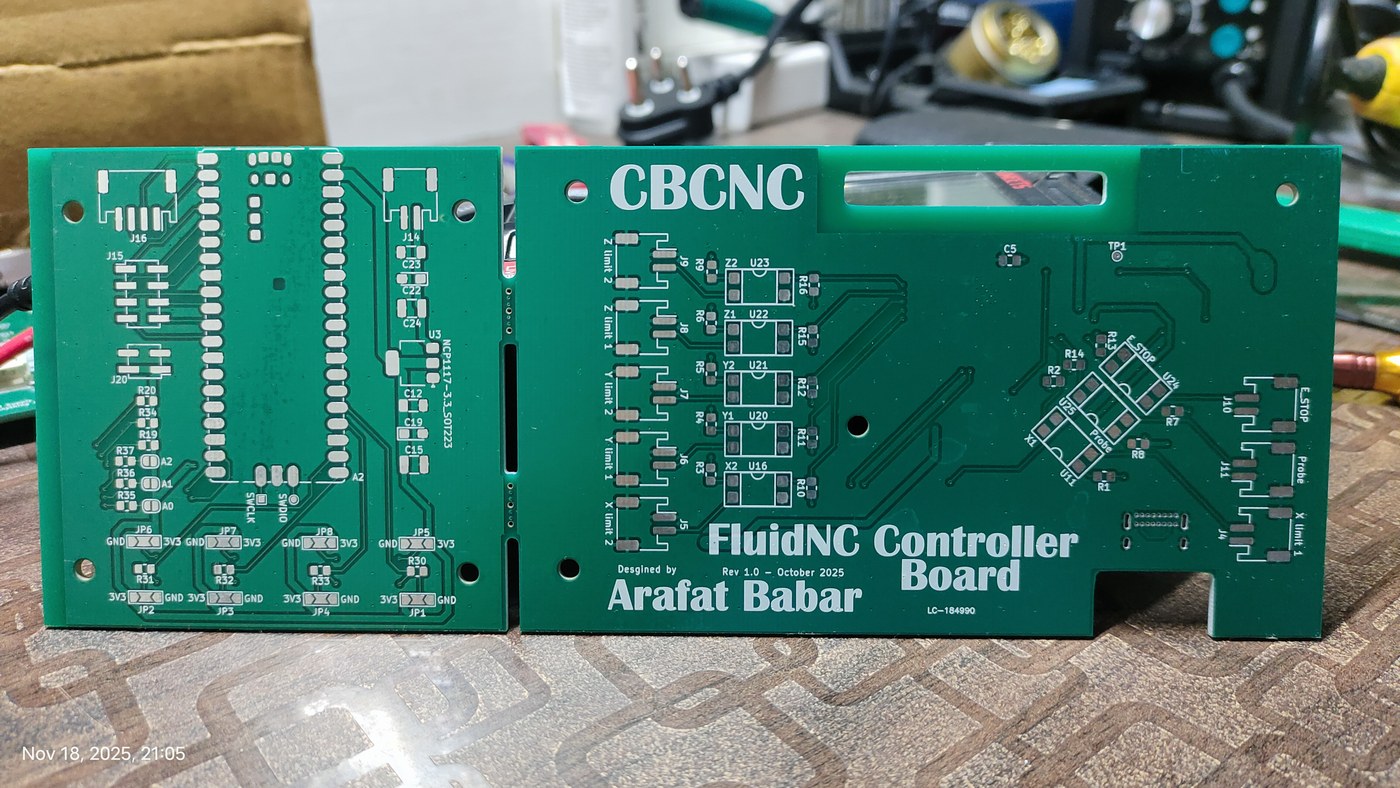
The first revision uses a custom two-layer controller PCB built around an ESP32-S3 module and running FluidNC firmware.
I was already familiar with the ESP32-S3 and considered it capable enough for the project. FluidNC was attractive because of its documentation and established CNC-control ecosystem. Using FluidNC allowed me to spend time understanding the machine and its physical integration rather than developing CNC firmware from scratch. (The controller PCB is a custom hardware design; I did not develop the FluidNC firmware itself).
- ESP32-S3 Core: Dual-core processor handling motion parsing, step generation, and USB communication.
- Optoisolated Limit Inputs: 6 optically isolated channels routed on PCB. (Physical limit switches were not tested).
- Logic-Level Translation: Dedicated circuitry stepping 3.3 V GPIOs up to 5 V for external stepper drivers.
- Stepper Driver Headers: Dedicated terminals interfacing to external DM542 microstepping drivers.
- HMI UART Header: Serial interface routed to secondary RP2040 operator pendant.
*Spindle Control Note: Spindle speed was manually adjusted via an external potentiometer rather than being integrated into closed-loop FluidNC G-code control.
To explore standalone machine interaction, I designed an RP2040-based HMI PCB connected to the main controller over UART. It includes provision for a display, status LEDs, and configurable buttons. In Rev 1, the HMI was only partially implemented; the more polished display, software experience, and simplified operator workflow belong to the Rev 2 vision.
Assembly, Integration & Hardware Challenges
Integrating mechanical parts, motor drivers, custom electronics, power supplies, firmware, and the HMI presented several practical engineering hurdles documented through workbench testing.
Tuning the motion system required managing a sensitive mechanical trade-off between alignment and friction. Tightening mounting screws too firmly increased rotational resistance along the lead screw, while leaving them slightly loose compromised axis alignment. Achieving acceptable movement required assembling and disassembling the axis mechanism more than 100 times to iteratively adjust lead-screw alignment and minimize mechanical binding.
During assembly, standoffs were tightened into the stepper motor without recognizing that the same threaded holes were being used to secure the motor assembly itself. As the standoffs were torqued, the internal threads stripped and the motor structurally separated, destroying the unit. This demonstrated the mechanical rule never to reuse the same threaded holes for multiple structural functions.
SECONDARY CHALLENGES (THREAD DEPTH & SOURCING) expand_more
While component datasheets specified minimum 4.5 mm thread depth, received motors exhibited threaded-hole depths varying between 7 mm and 9 mm across units. This made fastener length selection unpredictable and complicated alignment.
RECORD ID: dfmJgHhQSourcing mechanical parts, precision lead screws, and motor hardware required finding suppliers beyond hobby robotics stores, combining purchased components with custom 10 mm aluminum plates.
PROJECT SOURCING AUDITAfter procuring replacement motors, physical inspection revealed unexpected manufacturing variations. While the component datasheet specified a minimum thread depth of 4.5 mm, the received motors exhibited actual threaded-hole depths varying between 7 mm and 9 mm across units. This inconsistency made fastener length selection unpredictable and complicated motor mounting alignment, highlighting that catalog datasheets do not always guarantee real-world manufacturing uniformity.
Component availability was difficult, and sourcing mechanical parts, precision lead screws, and motor hardware required finding suppliers beyond initially explored hobby robotics stores. Combining purchased components, custom 10 mm aluminum plates, and manual assembly operations required careful organization to keep the physical assembly operable.
Testing & Current Results: Verified Capabilities vs. Unvalidated Targets
Rev 1 achieved basic axis movement and soft-limit operation under USB control. Selected voltages and currents were checked where needed, and the assembly was visually inspected.
A current measurement was conducted on the 300 W spindle under no-load conditions. Even without cutting material, the motor drew measurable current to overcome bearing friction, internal windage, and electrical losses, providing an empirical reference baseline for future load detection.
A qualitative bench test demonstrated coordinated X/Y axis motion while the spindle was concurrently running under manual potentiometer control, under no-load conditions. This test verified that multi-axis translation and spindle operation could run simultaneously without immediate electrical interference, though stability under actual cutting loads was not evaluated.
Multi-axis motion & soft limits established under USB control.
300W spindle rotation & no-load baseline current measurement.
0.2 mm PCB isolation milling, drilling, or contour routing.
Physical limit switches, homing cycles, or quantitative accuracy.
Budget, Project Support & Sourcing Realities
Awarded by Navrachana University through the Student Start-up and Innovation Policy (SSIP) prototype grant scheme to fund raw materials, components, and machining.
Approximate total including ~₹15,000–₹20,000 mechanical chassis parts, with the balance covering electronics, drivers, motors, power supplies, tooling, and iteration costs.
Engineering estimate for a streamlined single-unit build with optimized sourcing and fewer prototyping mistakes. (Future retail tier of ~₹1 lakh is a conceptual target only).
Rev 2: Design Evolution (CAD & Design Stage)
STRICTLY CAD PHASE // UNFABRICATEDRev 1 taught me that making the machine move is only one part of making a useful CNC machine. The motion system, mechanical rigidity, PCB mounting and alignment, controller architecture, safety arrangement, and operator experience all require substantial revision. Rev 2 is currently being developed in CAD.
MGN profile linear rails replacing round guide shafts to provide higher rigidity and reduce flexure under lateral cutting forces.
Ball screws instead of the Rev 1 lead-screw arrangement, aiming to reduce rotational friction and reduce backlash.
A stronger and more rigid frame structure to address the acoustic vibration observed during Rev 1 testing.
A redesigned bed to improve PCB mounting and registration when machining the reverse side of double-sided boards.
A revised controller architecture based on an STM32 microcontroller and GRBL HAL for dedicated, deterministic motion control.
A redesigned motor and motion-control arrangement, avoiding shared structural fastener points to prevent motor damage.
A standalone hardware E-stop arrangement instead of relying on controller firmware. (Electrical architecture and safety performance remain to be validated).
A more polished and modular HMI with a simpler operator workflow for standalone machine operation.
Reassessment of limit sensing, tool-length detection, and homing integration.
Lessons Learned & Closing Reflection
Rev 1 was a real electromechanical integration exercise. It required me to make trade-offs, source components, model the machine, integrate electronics and motion hardware, bring up firmware, and diagnose physical limitations on the bench.
The most valuable outcome was not a claim of successful PCB manufacturing. It was the understanding gained from turning a concept into a working motion prototype, diagnosing real-world physical and component failures, and using that empirical evidence to guide a more deliberate redesign.